
Distributor Replacement
by Brian Mills
This article describes the procedure for placing the distributor drive gear in the correct relationship to the gear on the camshaft. Simple eh?
Before I describe how to do this, let’s look at what the finished position of the distributor should be when we are done. In the TR2, TR3, and TR4 engines and in the 6-cylinder Triumph engines, an indication that the distributor is in the correct position is that the low-tension terminal on the distributor is at a 90 degree angle to the block of the engine.
Figures 1 shows the correct position. These diagrams also indicate the correct layout of the high-tension wires and the position of the rotor.
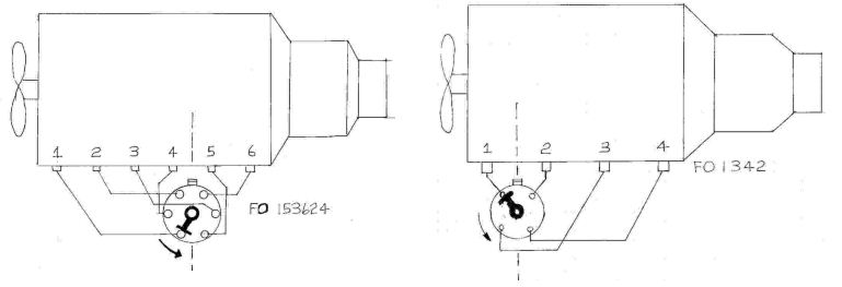
Figure 1: The correct position of the distributor, rotor, and high-tension wires on a Triumph 6-cylinder engine (left) and 4-cylinder-engine (right).
If the position of your distributor does not look like this, there is a possibility the rotor and the posts on the distributor cap will be misaligned. This can cause some strange problems.
Whenever you are removing the distributor, it is a very good idea to observe the position and alignment of all of the components. Note the distributor position, the wire connections, and the rotor positions.
To install (or correct) the position of the distributor gear, the engine is turned over so that it is at number 1 cylinder, top dead centre – compression (firing point). In this position, both valves in the number 1 cylinder are closed; therefore, both valve rockers will not be tight. Whereas, the cylinder at the other end of the block will be in crossover, and both valves will be slightly open, and the rockers will be tight.
Installing the distributor when you are rebuilding an engine is straightforward because the oil pump is installed after the distributor gear in installed. Simply put the gear in the position shown in Figure 2 (for a 4-cylinder engine) or Figure 3 (for a 6-cylinder engine). Be careful that the gear is well seated. The distributor drive gear also drives the oil pump.
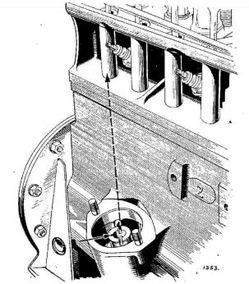
Figure 2: For a 4-cylinder engine, the driving slot is aligned with the push rod tube when number 1 piston is at top dead centre compressions stroke. Note the offset shown by the arrow.
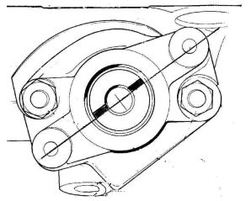
Figure 3: When the gear is properly installed in a 6-cylinder engine, the drive slot is aligned as shown (note the offset).
It is a little more of a challenge to fit the gear when the oil pump is installed. Because the teeth on the gear are bevelled, the gear rotates as it is being put into position. As well, the tang for the oil pump drive must be aligned such that it will engage ... more fun.
A few simple tools help a lot. A long 0.5-inch diameter bolt modified with a hacksaw will make a tool for aligning the oil pump drive. Note that the oil pump tangs are different for the 4 and 6 cylinder engines, so you will need to make modify the bolt to match your engine type (see Figure 4).
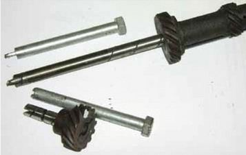
Figure 4: The distributor gears from a TR4 (top) and TR6 (bottom) with the modified bolts used to position the oil pump. Note the white dot on the TR6 gear to help reduce confusion when trying to align the gear.
The other tool that is very helpful is a strong magnet, which is used to hold the gear when you are putting it in place and also lifting it out. It usually takes several trys before you get it right, and the magnet is extremely useful for getting the gear back out.
Another small trick I use is to put ‘white-out’ on one tooth of the gear. This gives you a ready visual indication of where the gear ended up on the last try, and can save much confusion.
Be careful to ensure that the gear is seated properly. It takes some fiddling around to get the gear in just right, and you may need to take a break or two before you are finished.
Good luck.