Installing a Horn Relay in a TR3
by Brian Mills
Here are a series of simple instructions for installing a horn relay in a TR3.
1. Remove the horn fuse (the 50 amp one, yellow in Figure 1), or disconnect the battery.
2. At the right horn:
(a) Remove the horn grounding wire from the bullet connector (heavy Brown with Black trace). Ground this wire to the horn mounting bracket bolt with a round crimp lug (yellow 0.25 inch).
(b) No not remove the other horn wire (heavy Green with Black trace).
(c) Use a small black wire with a Lucas bullet connector to connect the heavy Brown with Black trace (attach this wire where the ground wire in step (a) was removed) to the place where you want to add the relay. If you locate the relay on the firewall adjacent to the flasher leave use about 3 feet or wire. Dress this sire along the original harness with black cable ties.
3. At the left horn:
(a) As at the right horn, remove the horn grounding wire from the bullet connector (heavy Brown with Black trace). Ground this wire to the horn mounting bracket bolt with a round crimp lug (yellow 0.25 inch).
(b) Leave the small Brown wire with Black trace (this wire comes from the horn push) connected to the heavy Brown wire with Black trace.
(c) No not remove the other horn wire (heavy Green with Black trace).
4. At the fuse box, voltage regulator, area:
(a) Remove the two heavy Brown with Green trace wires from the fuse holder. Twist these two wires together and add a short length of brown wire (16 gauge is OK). Solder this connection and insulate with heat shrink.
(b) Twist together two lengths of Red (16 gauge) wire and solder ends together. These wires are attached to the fuse holder where the green wires in step 4(a) were removed. These red wires connect provide power to the coil and contact terminal of the relay.
5. Locate and install the relay:
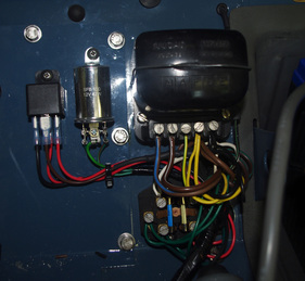
(a) The relay can be installed in any convenient location. One tidy spot is to locate it next to the flasher (Figure 1). Drill a pilot hole where you want to locate the relay and attach with a self-tapping screw.
(b) Dress the wires with cable ties (not too tight), and attach add crimp terminals to the two red and one brown wires.
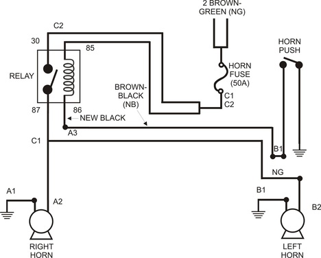
(c) The brown wire (connected to the heavy Brown wires with Green trace) is connected to the 87 terminal on the relay. One of the red wires from the fuse holder is connected to the 85 terminal of the relay, and the other red wire is connected to the 30 terminal of the relay. Finally the black wire from step 2(c) is connected to the 86 terminal of the relay (Figure 2).
(c) The brown wire (connected to the heavy Brown wires with Green trace) is connected to the 87 terminal on the relay. One of the red wires from the fuse holder is connected to the 85 terminal of the relay, and the other red wire is connected to the 30 terminal of the relay. Finally the black wire from step 2(c) is connected to the 86 terminal of the relay (Figure 2).
6. Reinstall the horn fuse, or reconnect battery … and Beep, Beep!


