Valve Timing Particular to Triumph Engines
By Brian Mills
For good performance of any automotive engine, the phasing of the crankshaft and the camshaft must be precise. When putting the engine back together two scenarios are possible. First (and most desirable), if: (1) a simple rebuild is being performed using the original sprockets and camshaft; (2) the engine has not been “messed with” and was not “lazy” before the rebuild; and (3) the sprockets were well marked before disassembly, then you should be able to use your shop manual as a guide for reinstallation and all will be OK.
However, if all of these conditions are not met, then the second case applies. In this case, you will need to: (1) determine precisely the top dead centre (TDC) position of both the crankshaft and the camshaft; (2) fit the sprockets and chain; and (3) verify that all of the components are in their correct position. This article explains how to handle this second scenario.
TDC — Crankshaft
In a 4 or 6 cylinder engine, the front piston (number 1 cylinder) and the rear piston (number 4 or 6 cylinder) are both at TDC at the same time in the rotation of the crankshaft. One cylinder will be firing (power stroke) and the other will be at the end of the exhaust stroke and the start of the intake stroke.
It is quite easy to determine TDC (in an engine with the head removed) with a dial gauge set on top of one of the pistons. An alternate method is to look at the timing marks on the flywheel and block.
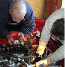
In an engine with the head on, a dial gauge fitted into the spark plug hole will also give a TDC indication (see Figure 1). This is a little more difficult and a specialized adapter for the dial gauge is needed, but it works well enough. The piston movement that needs to be measured is very small (in a TR6 with a 3.75 inch stroke, plus or minus 2 degrees of crankshaft rotation amounts to only 0.0012 inches of piston movement).
Figure 1: Gauge being used to determine TDC of cylinder one. Here I am working on Bob Thomas’ TR6.
TDC — Camshaft
Almost all camshafts have a symmetrical overlap at TDC. This means that the valves are open the exact same number of degrees on both sides of TDC. This relationship is used to determine the TDC of cylinder 1, because when both valves in the rear cylinder are open the exact same amount (it is completing exhaust and starting intake), cylinder 1 will be at precisely TDC with both valves closed (firing).
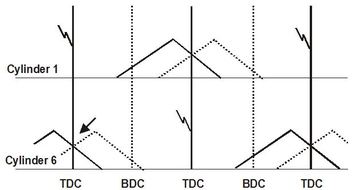
Here is how it works. At the rear of the engine, the exhaust valve is almost shut and the intake valve is just starting to open. The amount of “almost shut” and “almost open” is very small (remember they are equal at TDC). Although the cam lift at TDC crossover varies for different cam profiles, they are almost always the same magnitude (about 0.035–0.040 inches) for stock cams, and a little more for hot cams or racing cams. Figure 2 shows the relationship between the movements of cylinder 1 and cylinder 6 (or 4 if a 4 cylinder engine) as they complete a full cycle of a 4-stroke engine.
Figure 2: Relationship between valves opening and closing in cylinders 1 and 6. Exhaust valves are indicated by the solid “peaks” and the intake valves by the dashed “peaks”. The crossover point of the valves in cylinder 6 (indicated by the arrow) corresponds with TDC of cylinder 1. “Lightning bolts” represent approximate point at which the spark plugs fire.
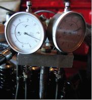
To find TDC for the camshaft, a pair of dial gauges are use to measure the cam lobe height of the rear cylinder. At this point, the rocker shaft, spark plugs, and timing chain have been removed. The mounting holes of the rear pedestal of the rocker shaft is used to mount the dial gauges (I have a custom-made setup for this, see Figure 3). In a headless block, the head bolts are used.
To find TDC for the camshaft, a pair of dial gauges are use to measure the cam lobe height of the rear cylinder. At this point, the rocker shaft, spark plugs, and timing chain have been removed. The mounting holes of the rear pedestal of the rocker shaft is used to mount the dial gauges (I have a custom-made setup for this, see Figure 3). In a headless block, the head bolts are used.
Figure 3: Gauges installed on cylinder 6 of Bob Thomas’ TR6 to measure the crossover point of the valves.
The next step is to zero the dial gauges when both valves in cylinder 6 are closed. Now you are able to determine the lift of the valves at the crossover point (0.035–0.40 inches is typical). As the camshaft is rotated, you will see that as one of the dial gauges starts to move up from zero, the other will start to move down from zero. The point you are looking for is when the movement in opposite directions is exactly the same. You will likely have to go through several sessions to find the exact point of crossover because a small movement of the cam results is quick movement of the valves at this point (both cam lobes are at maximum lift). If you miss the point keep going in a clockwise direction (don’t reverse the direction of the camshaft). When the TDC of the camshaft has been found, it is a good idea to do a few rotations of the camshaft just to verify that you are getting consistent readings.
Putting it All Together
When you are satisfied that you have good consistency, and the crankshaft is at TDC (based on the timing mark, see Figure 4), the timing chain can be refitted. Make sure that the gauges have not moved. Note that there are different possible locations for the camshaft sprocket on the camshaft (up to four) so some trial and error in fitting the camshaft sprocket and the timing chain may be necessary. Once the set up is considered correct, it is good practice to turn the crankshaft
a few more rotations to verify that when piston 1 is at TDC the lift crossover for the valves on the rear cylinder are identical. Remember that it takes two crankshaft revolutions for one camshaft revolution.
My experience has been that when the setup is correct, the gauges will all be at their proper places (with a thousands of an inch or so) over many revolutions. If this is not the case, something is not right.
See Brian's accompanying article on Distributor Replacement.


